此课程由化学与材料科学学院负责,面向化学专业本科生。
教学地点:七一路校区D5-327实验室
主要教材:《基础化学实验4——物性参数与测定》 马志广、庞秀言主编 化学工业出版社 2016年
下载
电导法测定弱电解质的电离平衡常数
实验思路
数据处理
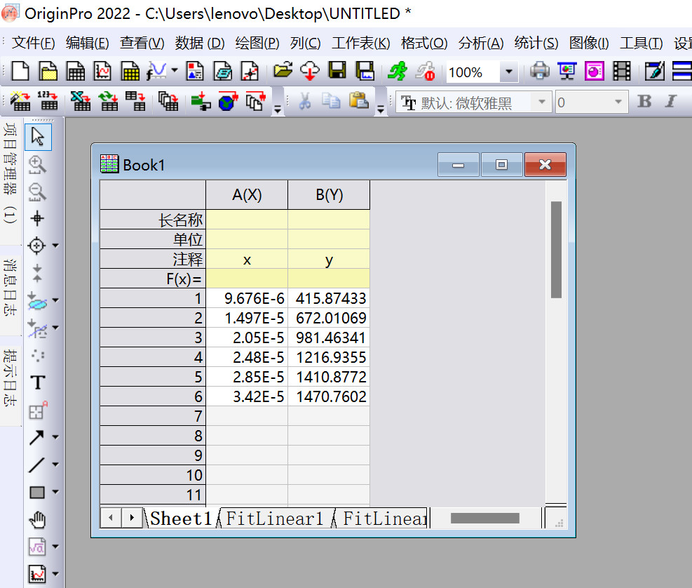
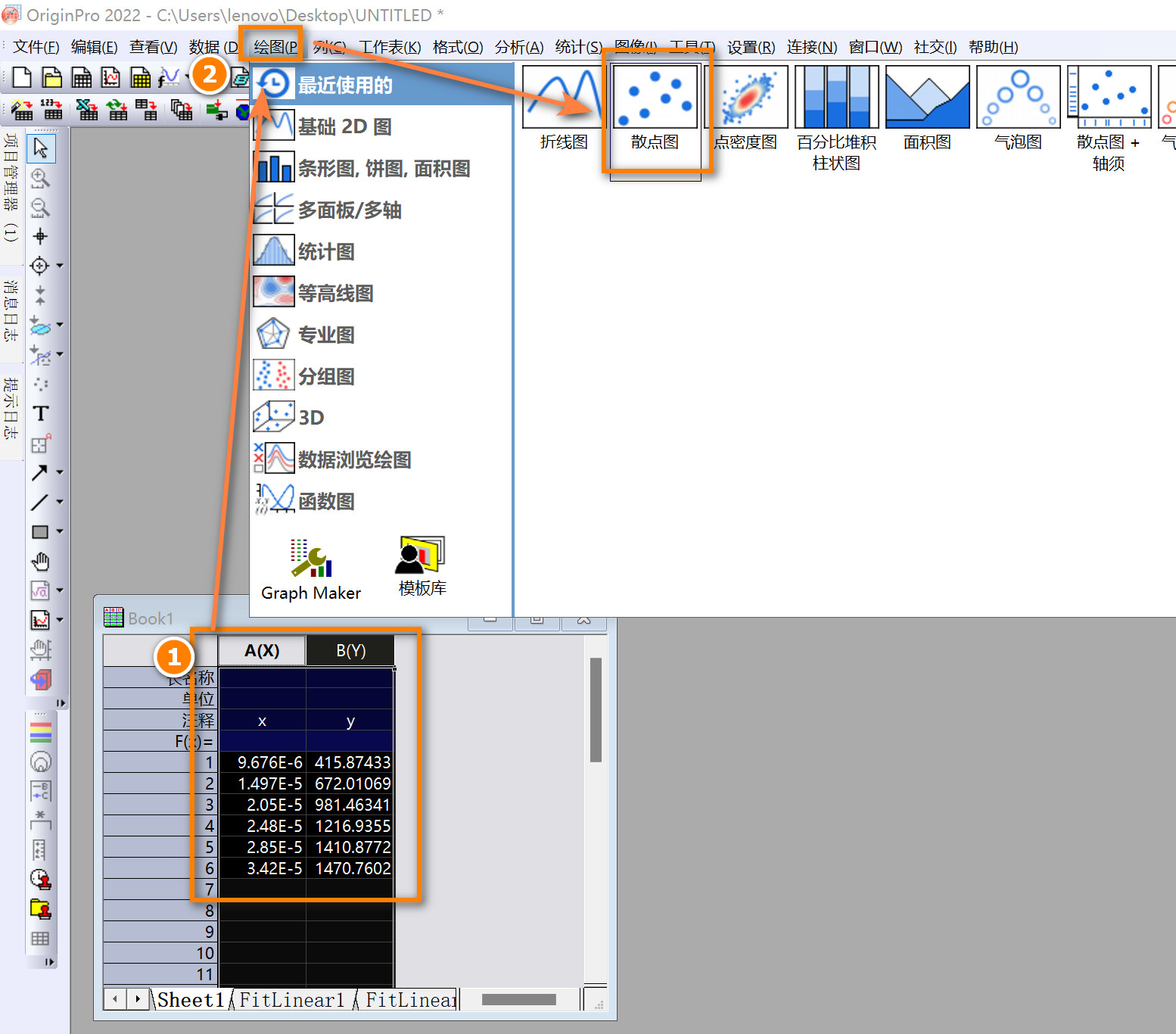
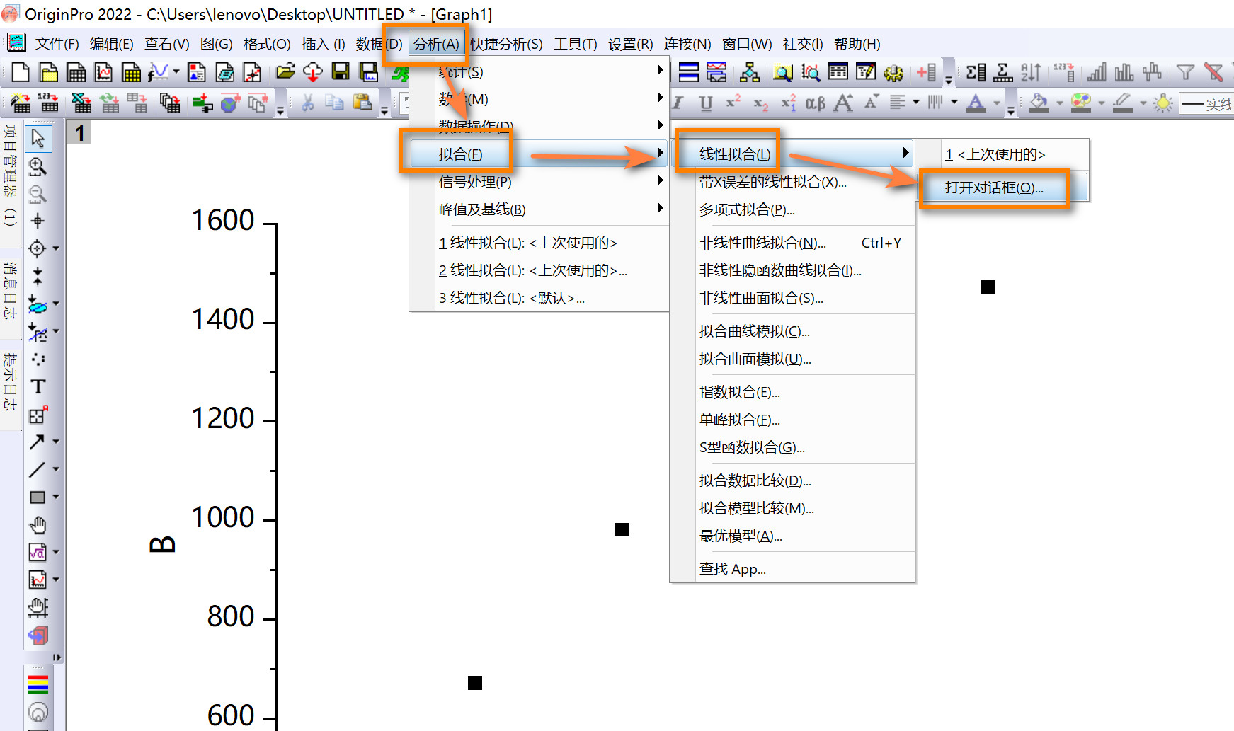
Origin作图
step1
step2
step3
step4
Python作图
 1
 2
 3
 4
 5
 6
 7
 8
 9
10
11
12
13
14
15
16
17
18
19
20
21
22
23
24
25
26
27
28
29
30
31
32
33
34
35
36
#!/usr/bin/env python
# -*-coding:utf-8 -*-
import os
import numpy as np
import matplotlib.pyplot as plt
os . chdir ( os . path . split ( os . path . realpath ( __file__ ))[ 0 ])
# 数据
data = [
[ 9.676E-6 , 415.87433 ],
[ 1.497E-5 , 672.01069 ],
[ 2.05E-5 , 981.46341 ],
[ 2.48E-5 , 1216.93548 ],
[ 2.85E-5 , 1410.87719 ],
[ 3.42E-5 , 1470.76023 ]
]
x , y = zip ( * data )
# 拟合数据
coefs = np . polyfit ( x , y , 1 )
fit_func = np . poly1d ( coefs )
# 绘图
plt . scatter ( x , y , color = 'tab:blue' , label = 'Data Points' )
plt . plot ( x , fit_func ( x ), color = 'tab:red' , label = f 'Fit: y = {coefs[0]:.4f}x + {coefs[1]:.4f}' )
plt . xlabel ( r '$c \times \frac{\Lambda_m}{c^{\ominus}}$' )
plt . ylabel ( r '$\frac{1}{\Lambda_m}$' )
plt . legend ()
plt . grid ( True )
# 保存到本地
plt . tight_layout ()
plt . savefig ( "result.jpg" , dpi = 300 )
plt . show ()
Matlab作图
 1
 2
 3
 4
 5
 6
 7
 8
 9
10
11
12
13
14
15
16
17
18
19
20
21
22
23
24
25
26
27
28
29
30
31
% 数据
data = [
9.676E-6 , 415.87433 ;
1.497E-5 , 672.01069 ;
2.05E-5 , 981.46341 ;
2.48E-5 , 1216.93548 ;
2.85E-5 , 1410.87719 ;
3.42E-5 , 1470.76023
];
x = data (:, 1 );
y = data (:, 2 );
% 拟合数据
fit_result = polyfit ( x , y , 1 );
fit_x = linspace ( min ( x ), max ( x ), 100 ); % 为拟合线生成x值
fit_y = polyval ( fit_result , fit_x );
% 绘图
figure ;
scatter ( x , y , 'b' , 'DisplayName' , 'Data Points' );
hold on ;
plot ( fit_x , fit_y , 'r' , 'DisplayName' , sprintf ( 'Fit: y = %.4fx + %.4f' , fit_result ( 1 ), fit_result ( 2 )));
xlabel ( 'c \times \Lambda_m / c^\o' );
ylabel ( '1/\Lambda_m' );
legend ();
grid on ;
% 保存到本地
filename = 'C:\Users\lenovo\Desktop\result.jpg' ;
print ( gcf , '-djpeg' , sprintf ( '-r%d' , 300 ), filename );
Mathematica作图
 1
 2
 3
 4
 5
 6
 7
 8
 9
10
11
12
13
14
15
16
17
18
19
20
21
22
23
24
25
26
27
28
29
30
31
32
(* 数据 *)
data = {
{ 9.676 * 10 ^ -6 , 415.87433 },
{ 1.497 * 10 ^ -5 , 672.01069 },
{ 2.05 * 10 ^ -5 , 981.46341 },
{ 2.48 * 10 ^ -5 , 1216.93548 },
{ 2.85 * 10 ^ -5 , 1410.87719 },
{ 3.42 * 10 ^ -5 , 1470.76023 }
};
(* 拟合数据 *)
fit = Fit [ data , { 1 , x }, x ];
coeffs = CoefficientList [ fit , x ];
(* 格式化拟合方程文本 *)
fitText = "Fit: y = " <> ToString [ N [ coeffs [[ 2 ]]]] <> " x + " <> ToString [ N [ coeffs [[ 1 ]]]];
(* 绘图 *)
plot1 = ListPlot [ data , PlotStyle -> { Blue , PointSize [ 0.015 ]}];
plot2 = Plot [ fit , { x , 9.676 * 10 ^ -6 , 3.42 * 10 ^ -5 }, PlotStyle -> Red ];
combinedPlot = Show [ plot1 , plot2 ,
AxesLabel -> {
"c \[Times] \[CapitalLambda]\!\(\*SubscriptBox[\(m\), \(\(c\)\(^\)\(\[CircleMinus]\)\)]\)" ,
"1/\[CapitalLambda]\!\(\*SubscriptBox[\(m\), \(\(c\)\(^\)\(\[CircleMinus]\)\)]\)"
},
GridLines -> Automatic ,
Epilog -> Text [ fitText , { 2.5 * 10 ^ -5 , 900 }]
];
(* 保存到指定的路径 *)
Export [ "C:\\Users\\lenovo\\Desktop\\result.jpg" , combinedPlot , ImageResolution -> 300 ];
Julia作图
 1
 2
 3
 4
 5
 6
 7
 8
 9
10
11
12
13
14
15
16
17
18
19
20
21
22
23
24
25
26
27
28
29
30
31
32
33
34
35
36
37
38
39
40
41
42
43
44
using Printf
using Plots
using LsqFit
using LaTeXStrings
# 数据
data = [
9.676E-6 415.87433 ;
1.497E-5 672.01069 ;
2.05E-5 981.46341 ;
2.48E-5 1216.93548 ;
2.85E-5 1410.87719 ;
3.42E-5 1470.76023
]
x = data [ : , 1 ]
y = data [ : , 2 ]
# 定义拟合模型
@ . model ( x , p ) = p [ 1 ] * x + p [ 2 ]
# 初始参数猜测
p0 = [ 1.0 , 1.0 ]
# 使用最小二乘法拟合数据
fit = curve_fit ( model , x , y , p0 )
# 获取拟合参数
coefs = fit . param
# 格式化拟合参数为字符串
coefs_str = string ( @sprintf ( " %.4f " , coefs [ 1 ]), "x + " , @sprintf ( " %.4f " , coefs [ 2 ]))
# 绘图
scatter ( x , y , color =: blue , label = "Data Points" , grid = true )
plot! ( x , model ( x , coefs ), color =: red , label = "Fit: y = $coefs_str " , grid = true )
xlabel! ( L "c \t imes \f rac{\Lambda_m}{c^{\ominus}}" )
ylabel! ( L " \f rac{1}{\Lambda_m}" )
# 保存到本地
savefig ( "C: \\ Users \\ lenovo \\ Desktop \\ result.png" )
# 显示图形
display ( current ())
using Plots下使用savefig保存的图有些小,可换其他绘图库。
蔗糖转化反应速率常数的测定
实验思路
蔗糖水解反应是一级反应,其反应速率常数与浓度有关;而浓度的实时测量需要与之成正比的旋光度α进行替换。
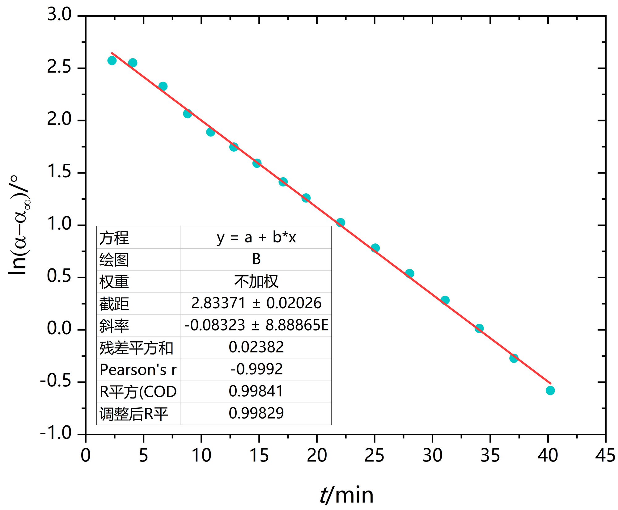
旋光度α的测量需要旋光仪。根据P51 式(7),需要测得一系列不同t时刻下的α和反应完全的α∞,代入式(7)作图,由斜率可得反应速率常数k。
根据上一步的k,再加上一级反应的特点(见P50 式(2))可知半衰期。
对于简单级数反应的半衰期:
零级反应的半衰期与反应的起始浓度成正比
一级反应的半衰期与反应的起始浓度无关
二级反应的半衰期与反应的起始浓度成反比
数据处理
Origin作图
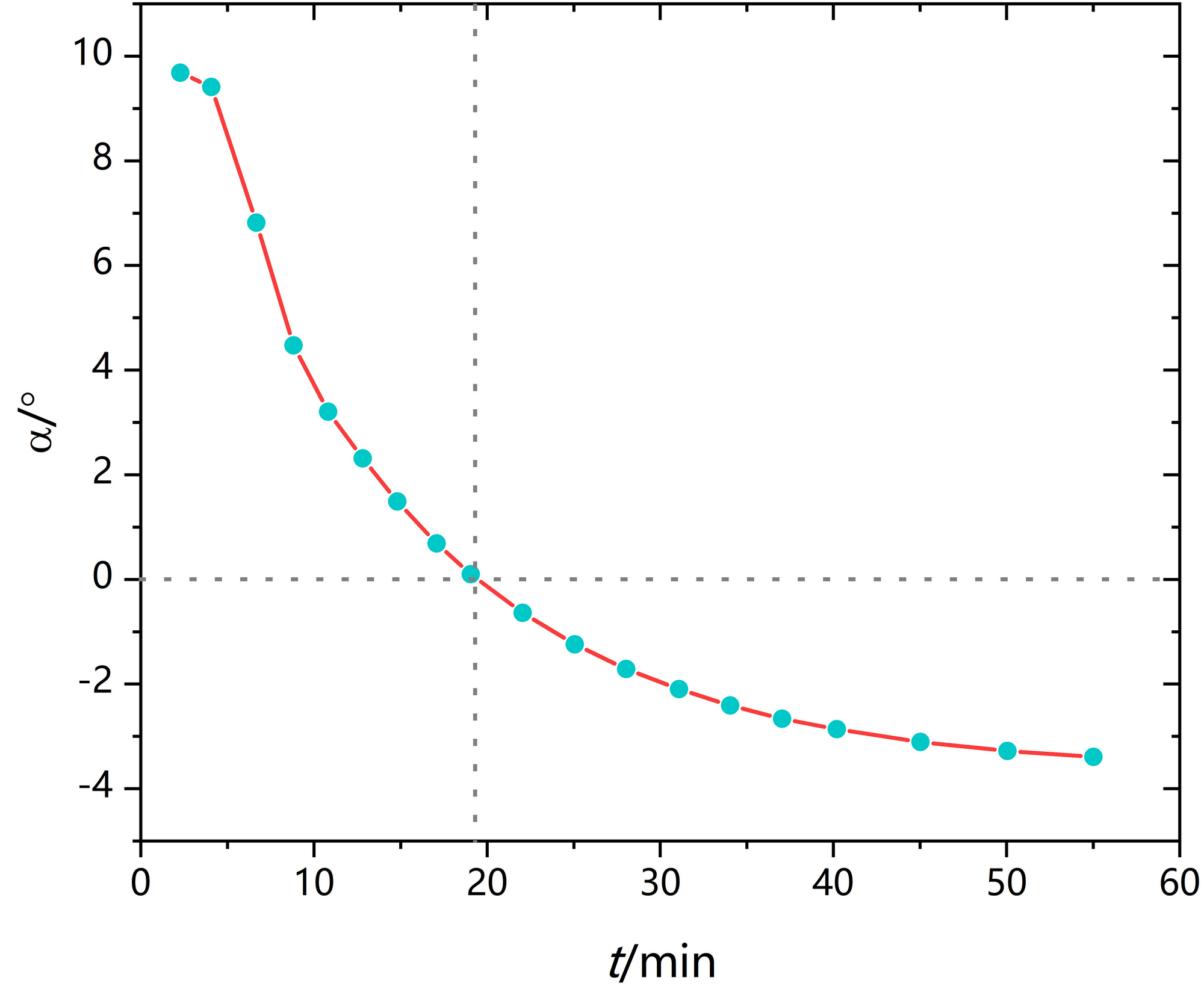
虚线不是必须,只是方便显示在19~20 min,旋光度由正变负。
2. 作α-t图
4. 作ln[(α-α∞)/°]-t
Python作图
 1
 2
 3
 4
 5
 6
 7
 8
 9
10
11
12
13
14
15
16
17
18
19
20
21
22
23
24
25
26
27
28
29
30
31
32
33
34
35
36
37
38
39
40
41
42
43
import matplotlib.pyplot as plt
# 数据
data = """
2.28 9.684
4.07 9.411
6.68 6.816
8.82 4.47
10.82 3.202
12.82 2.31
14.82 1.486
17.08 0.686
19.06 0.1
22.05 -0.638
25.06 -1.24
28.03 -1.713
31.1 -2.099
34.05 -2.411
37.05 -2.662
40.2 -2.864
45.03 -3.107
50.05 -3.278
55.02 -3.391
"""
# 解析数据
lines = data . strip () . split ( " \n " )
x , y = zip ( * [ map ( float , line . split ()) for line in lines ])
# 绘图
plt . plot ( x , y , color = 'tab:red' , label = 'Line through Data Points' )
plt . scatter ( x , y , color = 'tab:blue' , label = 'Data Points' )
plt . xlabel ( 't/min' )
plt . ylabel ( r '$\alpha$' + '/°' )
plt . legend ()
plt . grid ( True )
# 保存为300dpi的图像
plt . tight_layout ()
plt . savefig ( "C: \\ Users \\ lenovo \\ Desktop \\ pic1.jpg" , dpi = 300 )
# 显示图形
plt . show ()
 1
 2
 3
 4
 5
 6
 7
 8
 9
10
11
12
13
14
15
16
17
18
19
20
21
22
23
24
25
26
27
28
29
30
31
32
33
34
35
36
37
38
39
40
41
42
43
44
45
46
47
import numpy as np
import matplotlib.pyplot as plt
import os
os . chdir ( os . path . split ( os . path . realpath ( __file__ ))[ 0 ])
# 数据
data = """
2.28 2.57322
4.07 2.55218
6.68 2.3263
8.82 2.0661
10.82 1.891
12.82 1.74641
14.82 1.59127
17.08 1.41342
19.06 1.2596
22.05 1.02461
25.06 0.78116
28.03 0.53708
31.1 0.28141
34.05 0.01292
37.05 -0.27181
40.2 -0.57982
"""
# 解析数据
lines = data . strip () . split ( " \n " )
x , y = zip ( * [ map ( float , line . split ()) for line in lines ])
# 使用numpy进行线性拟合
coefs = np . polyfit ( x , y , 1 )
fit_func = np . poly1d ( coefs )
# 绘图
plt . scatter ( x , y , color = 'tab:blue' , label = 'Data Points' )
plt . plot ( x , fit_func ( x ), color = 'tab:red' , label = f 'Fit: y = {coefs[0]:.4f}x + {coefs[1]:.4f}' )
plt . xlabel ( 't/min' )
plt . ylabel ( r 'ln($\alpha$-$\alpha_{\infty}$)/°' )
plt . legend ()
plt . grid ( True )
# 保存为300dpi的图像
plt . tight_layout ()
plt . savefig ( "pic2.jpg" , dpi = 300 )
# 显示图形
plt . show ()
Python+Keras作图
 1
 2
 3
 4
 5
 6
 7
 8
 9
10
11
12
13
14
15
16
17
18
19
20
21
22
23
24
25
26
27
28
29
30
31
32
33
34
35
36
37
38
39
40
41
42
43
44
45
46
47
48
49
50
51
52
53
54
55
56
57
58
59
60
61
62
63
64
65
66
67
68
69
70
71
72
import numpy as np
import matplotlib.pyplot as plt
import tensorflow as tf
from tensorflow.keras.models import Sequential
from tensorflow.keras.layers import Dense
from tensorflow.keras.optimizers import Adam
import os
os . chdir ( os . path . split ( os . path . realpath ( __file__ ))[ 0 ])
# 数据
data = """
2.28 2.57322
4.07 2.55218
6.68 2.3263
8.82 2.0661
10.82 1.891
12.82 1.74641
14.82 1.59127
17.08 1.41342
19.06 1.2596
22.05 1.02461
25.06 0.78116
28.03 0.53708
31.1 0.28141
34.05 0.01292
37.05 -0.27181
40.2 -0.57982
"""
# 解析数据
lines = data . strip () . split ( " \n " )
x , y = zip ( * [ map ( float , line . split ()) for line in lines ])
# 转换数据为Keras所需的numpy数组形式
x = np . array ( x )
y = np . array ( y )
x = x . reshape ( - 1 , 1 ) # 重塑x为2D数组以匹配Keras输入需求
# 建立模型
model = Sequential ([
Dense ( 1 , input_shape = ( 1 ,), activation = 'linear' ) # 一个神经元,线性激活函数
])
model . summary () # 查看模型结构
# 编译模型
model . compile ( optimizer = Adam ( learning_rate = 0.1 ), loss = 'mse' )
# 训练模型
history = model . fit ( x , y , epochs = 1000 , verbose = 0 ) # 训练过程不显示
# 获取模型权重(斜率)和偏置(截距)
weights = model . get_weights ()
slope = weights [ 0 ][ 0 , 0 ]
intercept = weights [ 1 ][ 0 ]
# 使用模型进行预测
y_pred = model . predict ( x )
# 绘图
plt . scatter ( x , y , color = 'tab:blue' , label = 'Data Points' )
plt . plot ( x , y_pred , color = 'tab:red' , label = f 'Fit: y = {slope:.4f}x + {intercept:.4f}' )
plt . xlabel ( 't/min' )
plt . ylabel ( r 'ln($\alpha$-$\alpha_{\infty}$)/°' )
plt . legend ()
plt . grid ( True )
# 保存为300dpi的图像
plt . tight_layout ()
plt . savefig ( "pic2_ml.jpg" , dpi = 300 )
# 显示拟合曲线
plt . show ()
Matlab作图
 1
 2
 3
 4
 5
 6
 7
 8
 9
10
11
12
13
14
15
16
17
18
19
20
21
22
23
24
25
26
27
28
29
30
31
32
33
34
35
36
37
38
39
% 数据
data = [
2.28 , 9.684 ;
4.07 , 9.411 ;
6.68 , 6.816 ;
8.82 , 4.47 ;
10.82 , 3.202 ;
12.82 , 2.31 ;
14.82 , 1.486 ;
17.08 , 0.686 ;
19.06 , 0.1 ;
22.05 , - 0.638 ;
25.06 , - 1.24 ;
28.03 , - 1.713 ;
31.1 , - 2.099 ;
34.05 , - 2.411 ;
37.05 , - 2.662 ;
40.2 , - 2.864 ;
45.03 , - 3.107 ;
50.05 , - 3.278 ;
55.02 , - 3.391 ;
];
% 提取x和y
x = data (:, 1 );
y = data (:, 2 );
% 绘图
figure ;
plot ( x , y , '-r' , 'DisplayName' , 'Line through Data Points' );
hold on ; % 保持当前图形
scatter ( x , y , 'blue' , 'DisplayName' , 'Data Points' );
xlabel ( 't/min' );
ylabel ( '\alpha/°' );
legend ;
grid on ;
% 保存为300dpi的图像
print ( 'C:\Users\lenovo\Desktop\pic1.jpg' , '-djpeg' , '-r300' );
 1
 2
 3
 4
 5
 6
 7
 8
 9
10
11
12
13
14
15
16
17
18
19
20
21
22
23
24
25
26
27
28
29
30
31
32
33
34
35
36
37
38
39
40
% 数据
data = [
2.28 , 2.57322 ;
4.07 , 2.55218 ;
6.68 , 2.3263 ;
8.82 , 2.0661 ;
10.82 , 1.891 ;
12.82 , 1.74641 ;
14.82 , 1.59127 ;
17.08 , 1.41342 ;
19.06 , 1.2596 ;
22.05 , 1.02461 ;
25.06 , 0.78116 ;
28.03 , 0.53708 ;
31.1 , 0.28141 ;
34.05 , 0.01292 ;
37.05 , - 0.27181 ;
40.2 , - 0.57982 ;
];
% 提取x和y
x = data (:, 1 );
y = data (:, 2 );
% 使用MATLAB的polyfit进行线性拟合
coefs = polyfit ( x , y , 1 );
fit_values = polyval ( coefs , x );
% 绘图
figure ;
scatter ( x , y , 'blue' , 'DisplayName' , 'Data Points' );
hold on ;
plot ( x , fit_values , 'red' , 'DisplayName' , sprintf ( 'Fit: y = %.4fx + %.4f' , coefs ( 1 ), coefs ( 2 )));
xlabel ( 't/min' );
ylabel ( 'ln(\alpha-\alpha_{\infty})/°' );
legend ;
grid on ;
% 保存为300dpi的图像
print ( 'C:\Users\lenovo\Desktop\pic2.jpg' , '-djpeg' , '-r300' );
二元金属相图的绘制
实验思路
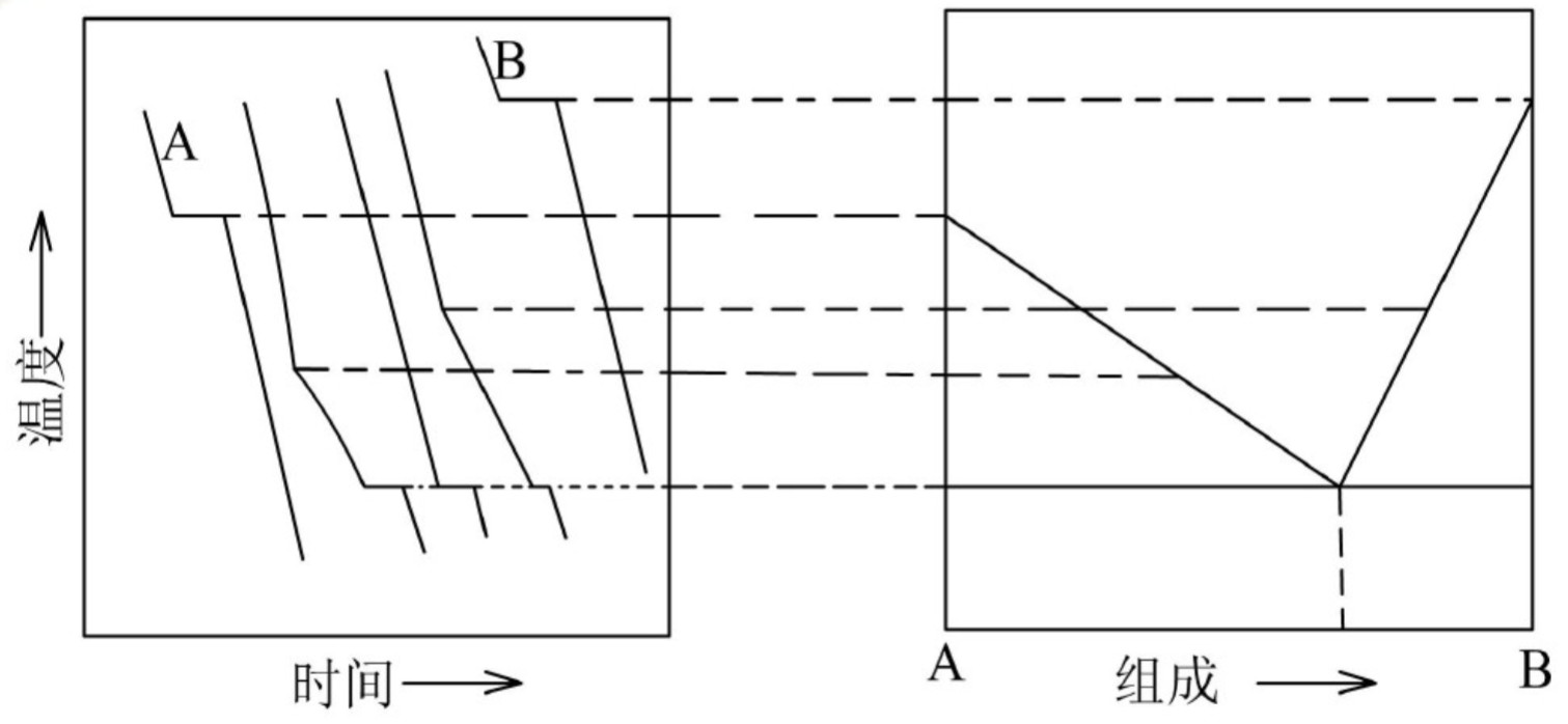
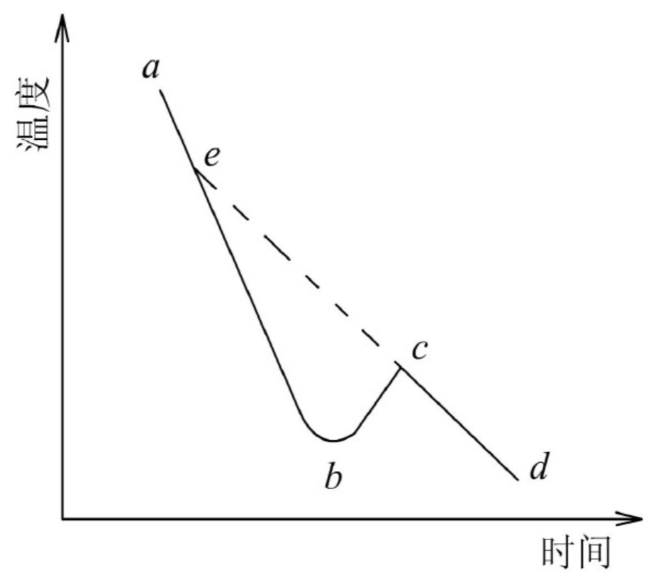
对步冷曲线的具体情况分析
严重过冷现象时的步冷曲线
8个样品的组成
Python代码会加载上面手机拍摄的图片“8个样品的组成”,将其转换为灰度图,然后将所有灰度值大于阈值(此处是150)的像素改为白色。这种方法对于清除背景中的轻微灰色噪点非常有效。如果你的图片有色彩,你可能需要调整这个方法来处理RGB值。
 1
 2
 3
 4
 5
 6
 7
 8
 9
10
11
12
13
14
15
16
17
18
19
20
21
22
23
24
25
26
from PIL import Image
def whiten_background ( image_path , output_path , threshold = 150 ):
# 打开图像
with Image . open ( image_path ) as img :
# 转换为灰度
gray_img = img . convert ( "L" )
# 加载图像数据
pixels = gray_img . load ()
# 获取图像的宽度和高度
width , height = gray_img . size
# 遍历每个像素
for x in range ( width ):
for y in range ( height ):
# 如果像素值大于阈值,则设置为白色
if pixels [ x , y ] > threshold :
pixels [ x , y ] = 255
# 保存修改后的图像
gray_img . save ( output_path )
# 使用这个函数,输入你的图像路径和输出路径
whiten_background ( "组成.jpg" , "组成新.jpg" )
设置仪器参数。温度:300℃;加热功率:250W;保温功率:0W
加热选择档旋至“1”档,加热1-4号样品至熔化,当样品温度降到250℃左右开始计时,每隔30 s记录一次4个样品的温度(为使拐点明显,停止加热后小心地取出2-4号样品管,摇动十几下)。1号纯Sn样品记录到约220℃;2-4号样品记录到约120℃。
加热选择档旋至“2”档,加热5-8号样品至熔化(为使拐点明显,停止加热后小心地取出5-7号样品管,摇动十几下),当温度降低到280℃左右开始计时,每隔30 s记录一次4个样品的温度。8号纯Bi样品记录到约260℃停止,5-7号样品记录需到约120℃。
关闭仪器电源。
装有二组分的样品管在温度到设定温度后须小心地用干燥的布垫着取出来摇晃5-10下,使二组分样品达到混合均匀。否则拐点不明显。
数据处理
Python作图
2.找出各步冷曲线中拐点和平台对应的温度值,填入下表。
样品编号
1
2
3
4
5
6
7
8
ωBi/%
0
15
25
42
55
70
85
100
拐点温度/℃
-
213
189
161
-
182
226
-
平台温度/℃
231
134
135
134
134
133
134
271
3.以温度为纵坐标,以组成为横坐标绘出 Sn-Bi相图。
 1
 2
 3
 4
 5
 6
 7
 8
 9
10
11
12
13
14
15
16
17
18
19
20
21
import matplotlib.pyplot as plt
import numpy as np
from scipy.interpolate import PchipInterpolator
# Data for Sn-Bi phase diagram
composition = [ 0 , 15 , 25 , 42 , 55 , 70 , 85 , 100 ] # Bi composition in percentage
melting_points = [ 231 , 213 , 189 , 161 , 134 , 182 , 226 , 271 ] # Melting temperatures
# Plotting the phase diagram
plt . figure ()
plt . grid ()
plt . plot ( composition , melting_points , marker = 'o' , color = 'tab:blue' )
plt . title ( 'Sn-Bi Phase Diagram' , fontsize = 14 )
plt . xlabel ( r '$\omega_{\mathrm{Bi}}/\%$' , fontsize = 12 ) # Bi as subscript
plt . ylabel ( 'T/°C' , fontsize = 12 )
plt . xticks ( fontsize = 12 )
plt . yticks ( fontsize = 12 )
# Save the figure
plt . savefig ( 'python1.jpg' , dpi = 300 )
plt . show ()
界面移动法测定离子迁移数
实验思路
待测0.1mol*L-1的盐酸溶液(加入几滴甲基橙使溶液显红色),注入迁移管中,要注意不得使管壁有气泡附着。
数据处理
Python作图
V/mL
0.10
0.20
0.30
0.40
0.50
0.60
t/s
368
740
1110
1480
1860
2230
t+
0.867
0.859
0.863
0.863
0.845
0.873
氢离子迁移数平均值:0.862。
1 A = 1 C/s
F = 96500 C/mol
t_迁移数 = cVF/(1000It)
L/cm
1.0
2.0
3.0
4.0
5.0
6.0
t/s
412
825
1250
1680
2140
2520
10^3*r/cm•s^-1
243
242
24
238
234
238
E/V
18
22
28
32
36
42
离子平均迁移速率:2.39*10-3 cm/s。
delta_L/ delta_t计算界面迁移速率。
 1
 2
 3
 4
 5
 6
 7
 8
 9
10
11
12
13
14
15
16
17
18
19
20
21
22
23
24
25
26
27
28
29
30
31
32
33
import matplotlib.pyplot as plt
import numpy as np
from scipy.stats import linregress
import os
os . chdir ( os . path . split ( os . path . realpath ( __file__ ))[ 0 ])
# Data for the plot
length = np . array ([ 1.0 , 2.0 , 3.0 , 4.0 , 5.0 , 6.0 ]) # L/cm
voltage = np . array ([ 18 , 22 , 28 , 32 , 36 , 42 ]) # E/V
# Linear regression to find the best fit line
slope , intercept , r_value , p_value , std_err = linregress ( length , voltage )
line = slope * length + intercept
# Plotting the data and the fit line
plt . figure ()
plt . grid ()
plt . plot ( length , voltage , marker = 'o' , linestyle = '' , color = 'tab:blue' )
plt . plot ( length , line , color = 'tab:orange' , label = f 'Fit: E = {slope:.2f}L + {intercept:.2f}' )
plt . title ( 'Voltage vs. Length' , fontsize = 14 )
plt . xlabel ( 'L/cm' , fontsize = 12 )
plt . ylabel ( 'E/V' , fontsize = 12 )
plt . xticks ( fontsize = 12 )
plt . yticks ( fontsize = 12 )
plt . legend ( loc = 'upper right' , fontsize = 14 )
# Save the figure
plt . savefig ( 'python2.jpg' , dpi = 300 )
plt . show ()
# Print the linear equation and R-squared value
print ( f "Linear Equation: E = {slope:.2f}L + {intercept:.2f}" )
print ( f "R-squared: {r_value**2:.3f}" )
线性方程:E/V = 4.74L/cm + 13.07。测得两电极间距:17.0 cm。
E(H+)=13.5V dE/dL(H+)=0.794V/cm
E(Cd2+)=93V dE/dL(Cd2+) =7.13V/cm
r=2.39*10-3 cm/s
U(H+)=3.2*10-3 (cm2 v-1 s-1)
U(Cd2+)=3.35*10-4 (cm2 v-1 s-1)


